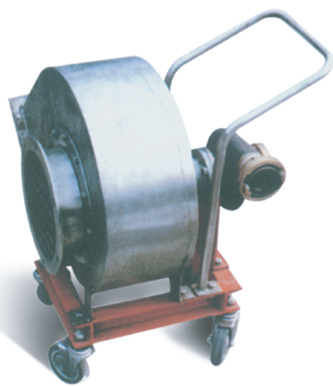

CSL TYPE MARINE EXPLOSION-PROOF CENTRIFUGAL FANS WITH WATER DRIVEN
CSL Series EPCV's i s a portable ventilator powered by fire-protection water.
| Basic parameters | |
| Ambient temperatures: | -25C~ +50C |
| Relative humidityof the air: | ≤95% |
| Cyclical vailltion: | 22.5 -45*(vcillation cycle 5~10S) |
| Sustained horizontal titing: | 15* |
| sustained vertical tting: | 10* |
| Vibration: | existence |
| Shock: | existence |
Detailed information
CSL series explosion-proof centrifugal ventilator fan enjoys high anti-hazard classification, sound anti-corrosion, anti- wobble, anti-vibration and anti-shock performance. The whole fan is featured in simple and compact structure, low weight, simple operation a s well as good movability. Driven directly by fire protection water, this ventilator is capable of ducting such dangerous gases as flammable and explosive gases or steam.
CSL ventilator fan is composed of water turbine, frame, casing, rotor, impeller, etc. The water turbine is precisely
cast of anti-corrosion copper alloy, the casing is soldered of austenitic stainless steel, and the impeller is cast of
high strength aluminum alloy, w ith the whole structure of no-spark design. The angles for air-outlet are R90°for
air supply and R225°f or air exhaust As a result, this type of ventilator can't change the model.
Structure:
CBL EPCV's have two types, Ty pe I (direct connection type ) and Type II (compartment type), The Fan is a no-spark design.
I(Direct Connection Type) The EPCV's is directly driven by the explosion-proof motor. In this t ype, The impeller is directly fixed on the motor shaft and the casing maunted on the flange of the explosion-proof motor.
The EPCV's structure is either in a horizontal, single-stage single-drawing and air tight structure, or in a structure.
The EPCV's can also be manufactured as compartment type, accordin g to the vertical 's requirements. In th e type, the EPCV and the motor are separated in different cabin with gearing customer's and sealing stuffing box as well as flexible couplings fixed in between.
The EPCV's can be set either left rotation or right rotation.
Left rotation, marked L, refers to the counter-clockwise rotation of t he impe ller from the view of the motor.
Right rotation, marked R, refers to th e clockwise rotation of the impeller from the view of the motor.
The position of the air outlet is basically made into the following types accordin g to the different rotation of the impeller.According to the requirements, the outlets can adopt other forms changing with 30°or 22.5°increment.
